
Your strip burner has one of two basic types of front suspensions holding it to the road. Most cars produced before the mid-to-late seventies were equipped with what we call a parallelogram type suspension, while most passenger cars produced since then have had rack and pinion suspensions. The easiest way to describe the differences between the two is to describe the mechanism that actually pushes the wheels left and right as you steer. Parallelogram suspension uses a steering rack to steer.

The Basic Parts of a Parallelogram Suspension
Other than the steering column, which both suspension types share, there are two “sections” of a parallelogram steering suspension: the worm gear/steering gear box and the parallelogram assembly. The steering parallelogram assembly consists of:
- Four tie rod ends-two inner and two outer
- An idler arm mounted on the passenger side of the vehicle
- A Pitman arm mounted to the bottom of the steering gearbox
- A drag or center link connecting everything else

The tie rod ends in a parallelogram steering setup have ends that are reverse-threaded – one is right hand and the other is left. They are connected by a threaded sleeve that is used to adjust steering toe during an alignment. The Pitman arm connects to the drag/center link and is what moves the parallelogram to steer the vehicle when you turn the steering wheel. The idler arm simply supports the passenger side of the parallelogram.

How the Parallelogram Steering System Works
When the driver of a car equipped with this type of steering system makes a steering input, the steering wheel turns the steering shaft/steering input shaft which is connected to the steering gearbox/worm gear input shaft. The turns a worm gear that meshes with another gear connected to the output shaft. As the worm gear turns, the gear causes the output shaft to turn.

At the other end of the output shaft is the Pitman arm. This is connected to the drag/center link which spans the vehicle side to side. The passenger side of the drag link is supported by the idler arm which is mounted on the passenger side frame rail. At either end of the drag link is an inner tie rod end. The inner tie rod end is connected by threaded sleeve to the outer tie rod end, which is in turn connected to the steering knuckle. When you turn the wheel, the Pitman arm is turned in the corresponding direction, thus moving the steering linkage (parallelogram) and thus turning the wheels to make the desired turn.
The Basic parts of the Rack and Pinion Suspension

The rack and pinion system is both simpler and more complex than the parallelogram system. It’s simpler because there are fewer components involved that we can see: the steering rack and two tie rod ends. It’s more complex for the same reason: There are parts of the system that we can’t see inside the steering rack.

These internal parts are the rack and pinion themselves, and two outer tie rods. These outer tie rods connect by a rotatable shaft to the outer tie rod ends. The rotating shaft is used to adjust toe during an alignment.
How the Rack and Pinion Steering System Works
The rack and pinion system is much easier to visualize. The driver commands a turn, turning the steering column which is connected to the pinion input shaft. Inside the steering rack body at the other end of the input shaft, the pinion rests against the steering rack. The steering rack is simply a long bar with gear teeth cut into it. As the steering pinion is turned, the teeth push the rack one way or the other.
Just inside the rack housing at either end of the steering rack there are two inner tie rod/sockets. Extending out from each of these is a rod that is threaded at the end. Threaded onto that rod is the outer tie rod end, which in turn is connected to the steering knuckle. Thus, as the steering rack is pushed one way or another, the rack and tie sockets push or pull the steering wheel, causing the wheels to turn and the vehicle to make the desired turn.
How Steering System Wear Presents Itself as You Drive
In a word, looseness. You’ll feel like you have to turn the wheel too much to get the desired turn. Another way you can tell you might have a problem with the steering system is if the car “jumps” back and forth as you drive in a straight line. Wear causes the parts to loosen. Each of the parts in both types of systems is considered a “wear item”. However, it’s pretty rare to need to swap out or repair a gearbox or steering rack.
Diagnosing Steering Problems with Parallelograms

So you’ve noticed a certain “squishiness” in your steering and you want to know why. Figuring out which component(s) has/have gone bad is quite easy. It’s just a matter of push, pull, and squeeze. To check the idler arm, grab the joint where it meets the rest of the parallelogram and push and pull it up and down with moderate force. Don’t muscle it, though. You shouldn’t be able to cause up and down motion using only moderate force. If you can, it needs to be replaced. What’s happening is that it’s bouncing up and down as you drive, pushing and pulling the wheels in and out while the car moves.

Everything else in the parallelogram is diagnosed by squeezing, by hand. If someone tells you to use something like a pair of Channellocks to check the Pitarm, drag link, or tie rods, hit them with it. Grasp the part, let’s say tie rod end in your fist, and squeeze. The only movement you should feel should be the squishiness of your hand, nothing more. If you feel a slight lick or thump in either your palm or your fingers, replace the part. Worn tie rod ends or a worn Pitman arm can manifest as either both wheels wiggling in and out (Pitman arm) or just one (tie rod ends).
Replacing Parallelogram Components
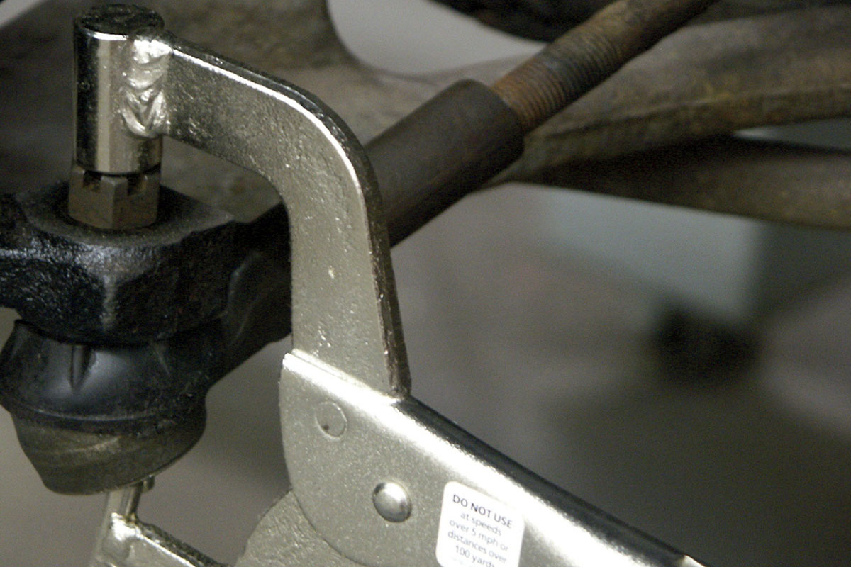
Replacing everything but the Pitman is actually really easy. Remove the cotter pin that keeps the castellated nut from turning and loosen the nut a few threads. Using either a tie rod separator or a pickle fork, separate the tie rod from the component it’s attached to, Pitman arm, idler arm, steering knuckle.
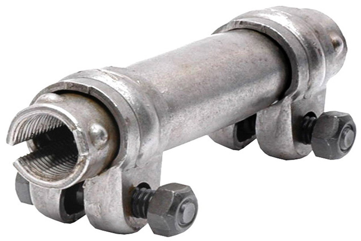
If you’re replacing tie rod ends, first make note of approximately how many threads are exposed outside the adjuster sleeve. Now loosen the tie rod adjuster sleeve nuts and bolts and spin the tie rod off. Thread the new tie rod into the sleeve until the same number of threads are exposed and snug the adjuster sleeve bolts up. Slip the tie rod stud through the corresponding hole and thread the castellated nut on. Tighten the nut to approximately 40 lb-ft of torque.

To finish up, tighten the nut in small increments until the hole in the stud is exposed and slide a cotter pin through the nut and stud and bend the ends over or around the nut/stud. After replacing what needs to be replaced, set the toe and you’re done.
Replacing the idler arm is similar, except there’s no threaded sleeve to worry about. Most idler arms are bolted to the frame with either two or three bolts. Disconnect the idler from the drag link using the tie rod separation procedure them remove the bolts. Put the new idler in by reversing the steps: bolt it to the frame and reconnect it to the parallelogram.

Diagnosing Problems Rack and Pinion Steering
The only difference between most rack and pinion problems and parallelogram problems is in the way inner tie sockets are diagnosed. The outer tie rod ends are diagnosed the same way, by squeezing and feeling for movement or clicking in the joint.

To diagnose the inner sockets, turn the wheel so the rack is fully extended towards you. Next, firmly squeeze the dust boot until you can feel the socket and connecting rod. Now, squeesing the tire between your body and one hand, push and pull the wheel in and out. You should feel absolutely no movement in the tie socket. If you do, it’s worn and needs to be replaced.
Replacing Worn Rack and Pinion Components
Replacing the outer tie rod ends on a rack and pinion system is the same as for parallelogram systems, the difference lies in replacing the inner tie socket. Remove the clamps securing the dust boot to the rack housing and the extension rod and slide it outboard as far as it will go.
Remove the locking pin that extends through the socket and rack, with a small punch and hammer. You don’t want to hit it with much force, just enough to get it to slide out enough to remove with pliers. Next, grasp the steering rack with either an adjustable wrench or an open end wrench, but NOT pliers. Using another wrench, loosen and remove the inner socket from the rack. Make note of how many threads on the extension rod are exposed at the tie rod end and remove it from the tie rod end. You can, but don’t need to, remove the outer tie rod end from the steering knuckle.

Slide the dust boot over the new extension rod. Thread the extension rod of the new inner socket into the outer tie rod end until the same number of threads are left exposed as were on the old one, but don’t lock it down yet. Thread the new inner socket onto the steering rack until hand tight. Finish tightening the inner socket by holding the steering rack with a wrench and tightening the socket. Now, keep tightening in very small increments until the lock pin hole in the new socket lines up with the hole in the rack. Tap the lock pin back into place and secure the dust boot in place with the clamps. Finally, set the toe according to spec. this article is an original post from 2015 from Mike Aguilar
Hey what a brilliant post I have come across and believe me I have been searching out for this similar kind of post for past a week and hardly came across this. Thank you very much and will look for more postings from you Best Auto Hail Damage Removal Cheyenne service provider.
ReplyDeleteGreat article by the great author, it is very massive and informative but still preaches the way to sounds like that it has some beautiful thoughts described so I really appreciate this article. Best auto mechanic shop near me service provider
ReplyDeleteThis is excellent information which is shared by you. This information is meaningful and magnificent for us to increase our knowledge about it. Keep sharing this kind of information. Thank you. Audi Service Centre Delhi
ReplyDeleteThe content you've posted here is fantastic because it provides some excellent information about Mobile Auto Technician in USA that will be quite beneficial to me. Thank you for sharing that. Keep up the good work.
ReplyDeleteIt's very nice of you to share your knowledge through posts. I love to read stories about your experiences. They're very useful and interesting. I am excited to read the next posts. I'm so grateful for all that you've done. Keep plugging. Many viewers like me fancy your writing. Thank you for sharing precious information with us. Best Automotive Glass Repair Cheyenne service provider.
ReplyDeleteThis comment has been removed by the author.
ReplyDeleteYou have provided valuable data for us. It is great and informative for everyone. Keep posting always. I am very thankful to you. Read more info about Car Rental Dalaman
ReplyDelete